Antwort What is the main difference between PFD and P&ID drawings? Weitere Antworten – What is the difference between P and ID and PFD
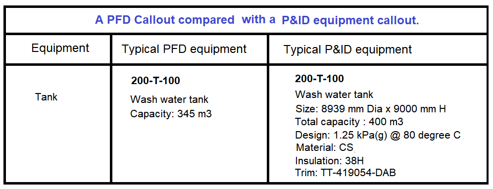
PFDs serve as the initial tool used to create the specifications and data sheets for all the process related equipment; P&IDs further enhance the specifications and data sheets. They initiate the definition of all piping, instrumentation, control valves, and electrical components.Generally, a Process Flow Diagram shows only the major equipment and doesn't show details. PFDs are used for visitor information and new employee training. A Process and Instrument Drawing (P&ID) includes more details than a PFD. It includes major and minor flows, control loops and instrumentation.You can quickly draw P&IDs and PFDs by dragging process engineering equipment shapes onto your drawing page, connecting them with "smart" pipelines, and then dragging components, such as valves and instruments, onto the pipelines. To identify components in your diagram, you can create intelligent tags.

What is the full form of PFDs : /ˌpiː ef ˈdiː/ a life jacket or similar device that is designed to help you float in water (the abbreviation for 'personal flotation device') All competitors are required to wear PFDs and helmets.
What is P & ID
Piping and Instrumentation Diagram
P&ID is an abbreviation meaning 'Piping and Instrumentation Diagram'. Piping and Instrumentation Diagrams are graphical representations of a process system. These are fundamental to every standardized engineering project.
What is the advantage of P and ID : Making processes visible
When complete, the piping & instrumentation diagram acts as an important reference document for all downstream design tasks such as equipment layout and the routing of pipework. It is also used to prepare parts lists to assist with choosing suitable components and for project costing purposes.
Simplified or conceptual designs are called process flow diagrams (PFDs). A PFD shows fewer details than a P&ID and is usually the first step in the design process–more of a bird's eye view. More fully developed piping and instrumentation diagrams (P&IDs) are shown in a P&ID.

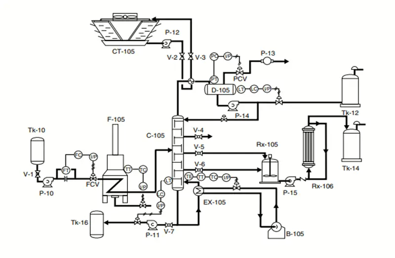
P&ID is short for “Piping and Instrumentation Diagram”. A P&ID uses simple graphics to represent complex processes and convey the flow of material through a process. It shows the equipment used in the process, and all of the signals required to measure and control the process.
What is the PFD P&ID
Both PFD (Process Flow Diagram) and P&ID (Piping/Process & Instrumentation Diagram) are chemical / process engineering drawings.Process flow diagrams (PFD) describe a manufacturing process in terms of the various steps involved and the inputs and outputs from those steps. This is often the initial document generated in a new process, as it gathers the data known, sets the process operating conditions, and allows the sizing of equipment.A lifejacket, also known as a Personal Flotation Device (PFD) or buoyancy vest, will keep the user afloat in the water, greatly increasing their likelihood of survival. As the name suggests, it can save your life in the case of an emergency, giving you more time to be rescued.
A TYPE III PFD, or FLOTATION AID, is good for calm, inland water, or where there is a good chance of quick rescue. This PFD type will not turn unconscious wearers to a face-up position. The wearer may have to tilt their head back to avoid turning face down. TYPE III has the same minimum buoyancy as a TYPE II PFD.
What is P and ID PDF : • Piping And Instrument Diagram (P&ID) Is A. Schematic Diagram That Shows How. Equipment And Instruments Connect To Form. A Functional Process System. • The P&ID Is The Chief Control Document For.
What is the role of P and ID in safety : Operations, Safety And Maintenance
Piping and Instrumentation Diagram is also a guide for operational data. They are used in the training of facility operating staff, field engineers, and maintenance professionals. P&ID is the fundamental document for HAZOP, Model review, and Process Safety Management.
What is the basic of P and ID
A piping and instrumentation diagram (P&ID or PID) is a detailed diagram in the process industry which shows the piping and process equipment together with the instrumentation and control devices. It is also called as mechanical flow diagram (MFD).

P&ID is an abbreviation meaning 'Piping and Instrumentation Diagram'. Piping and Instrumentation Diagrams are graphical representations of a process system. These are fundamental to every standardized engineering project. These two-dimensional diagrams function as a blueprint for the engineering system's design.In Unix and Unix-like operating systems, a process ID (PID) is a unique positive integer assigned to each process when it is created. The PID is used to identify a process and to allow the operating system to track and manage the process.
What is the meaning of PFD drawing : A Process Flow Diagram (PFD) is a type of flowchart that illustrates the relationships between major components at an industrial plant. It's most often used in chemical engineering and process engineering, though its concepts are sometimes applied to other processes as well.


